2026.10.13 Linear ATC Auto-Loading CNC Routers Layout Design and Collision Avoidance
2026-10-15
When investing in high-efficiency CNC routers for panel furniture, cabinet making, and signage production, factory owners often choose between Linear ATC CNC Routers and Auto-Loading CNC Routers. While both deliver automated machining to cut labor costs, they differ drastically in footprint requirements, working zone layout, moving axes range, and potential collision hazards. Proper layout planning and collision control directly determine machine uptime, operator safety, and equipment service life. This guide breaks down layout design principles and collision avoidance strategies for both machine types.
1. Core Structure Difference
Linear ATC CNC Router
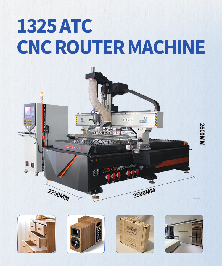
Linear ATC adopts a linear tool magazine mounted alongside the gantry. Tools are arranged in a straight line. The spindle travels along the linear rack to pick up and change tools automatically.
- Tool magazine moves together with spindle / spindle moves to fixed linear tool rack
- Tool change happens outside the workpiece cutting area
- Main moving parts: gantry, spindle, linear tool bank
Auto-Loading CNC Router
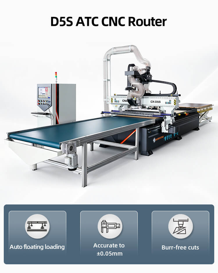
Auto-loading CNC integrates automatic loading & unloading platform, roller feeding system, and processing table. It can automatically feed raw panels, machine parts, and discharge finished boards without manual panel handling. Many auto-load models also come with ATC spindle.
- Dual zone design: loading zone + machining zone
- Extra moving components: feeding rollers, pushing cylinders, material positioning stops, unloading conveyor
- Larger number of actuators, more interlinked motions
2. Workshop Layout Design
Linear ATC CNC Router Layout
1. Space Requirement
Reserve extra space on one side of the machine for the linear tool magazine stroke. The tool rack stretches horizontally, so you need clear clearance along the X-axis side.
- Front: Operator access, 800–1000mm walkway
- Tool magazine side: ≥600mm clearance, no stacked materials or fixtures
- Rear: Cable drag chain & electrical cabinet space, ≥500mm
- No overhead obstructions above full gantry travel range
2. Layout Tips
- Place the machine parallel to the workshop wall; keep the linear tool magazine facing the open aisle, not the wall.
- Reserve space for dust collector connection on the side opposite the tool rack.
- Suitable for small & medium workshops with limited floor space, single-station processing.
Auto-Loading CNC Router Layout
1. Space Requirement
Auto-loading models occupy a longer total length because of front loading and rear unloading platforms.
- Infeed side: Raw material stacking area, enough space for panel feeding
- Machining zone: Main working table
- Outfeed side: Finished product stacking area
- Both sides need free space for material pushing mechanisms
2. Layout Tips
- Best arranged as a straight production line: raw material → auto loading table → machining table → unloading → finished goods.
- Separate walkways from material transport path to avoid operator crossing the automatic material movement area.
- Leave space for auxiliary equipment: dust extraction, air compressor, vacuum pump.
- Recommended for large panel furniture factories with continuous batch production.
3. Potential Collision Risks
Linear ATC Collision Points
1. Spindle & Linear Tool Magazine Collision
The most common risk: wrong tool change coordinate setting causes spindle to crash into tool holders.
2. Spindle Collision with Workpiece / Clamps
Incorrect Z-axis zero point, wrong CAM nesting depth, leftover fixtures on the table.
3. Gantry collision with side barriers
X-axis travel limit parameter error.
Auto-Loading CNC Collision Points
Auto-loading machines have more collision risks due to multi-action linkage:
1. Pushing cylinders / material stoppers collide with spindle during machining.
2. Feeding rollers push panels while spindle is still cutting.
3. Workpiece shifts during auto feeding, spindle hits misplaced panel.
4. Unloading mechanism interferes with gantry movement.
5. Material stacking blocks auto infeed path.
4. Collision Avoidance Solutions
Universal Safety Settings
- Set hardware limit switches + software soft limits for X/Y/Z axes.
- Run dry air cutting simulation without material before formal production.
- Use vacuum hold-down to fix panels firmly, prevent workpiece shifting.
- Regularly calibrate tool length offset and workpiece origin.
- Keep the machine table clean; remove scraps, broken tools and leftover jigs.
For Linear ATC CNC
1. Lock tool change zone coordinates; restrict spindle movement range during tool swap.
2. Set dedicated safe height for spindle when traveling to linear tool rack.
3. Check tool magazine alignment monthly; make sure each tool holder is secured.
4. Program interlock: machine cannot start cutting if tool change is incomplete.
For Auto-Loading CNC
1. Enable motion interlock logic: feeding/unloading actions are disabled when spindle is in working area.
2. Install photoelectric sensors on loading zone to detect misplaced or oversize panels.
3. Add physical safety fences around auto feeding/unloading sides.
4. Separate G-code programs: loading cycle, machining cycle and unloading cycle with safety trigger conditions.
5. Train operators not to place any objects on loading/unloading platform during machine operation.
5. Quick Comparison Table
|
|
Linear ATC CNC Router |
Auto-Loading CNC Router |
|
Layout Footprint |
Medium, extra space required for linear tool rack |
Large, full line space for infeed & outfeed |
|
Working Station |
Single station |
Dual station (loading + processing) |
|
Main Collision Risk |
Spindle to linear tool magazine |
Material pushers & spindle interference |
|
Production Mode |
Intermittent production |
Continuous batch automatic production |
|
Best For |
Custom sign, small batch cabinetry |
Mass panel furniture manufacturing |
6. Conclusion
Linear ATC CNC routers feature a compact layout with collision risks mainly concentrated on the linear tool changing system. It is easier to install and suitable for factories with limited workshop space. Auto-loading CNC routers improve automation and throughput, yet require careful whole-line layout design and multi-motion interlock protection to avoid collision between material handling components and the spindle.
Select your machine according to workshop size, batch volume and available manpower. Correct layout planning and safety parameter configuration are the most cost-effective ways to reduce crash accidents and extend CNC machine service life.